Creating Buttons and Switches
The GPIO board is a bit different than the display and the audio amp... it is not a ready-made breakout board, but instead one we need to assemble. We need the following parts (some of which are on the Hack Clock's v2 Wishlist):
- A mini breadboard
- A few push buttons
- One or two N-channel MOSFETs (or a relay switch)
- A 4.7k resistor for each MOSFET (probably won't need this for a relay)
- Some short lengths of insulated wire
Input (Buttons)
Let's wire up some buttons. The buttons will connect a general purpose input/output (GPIO) pin to a ground pin. Once the GPIO pin is connected to ground, our alarm clock will notice a button has been pressed and react likewise.
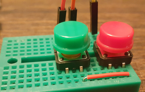
The tactile buttons in the hardware list have four pins, two on each side. Note that a pin on one side is always connected to the other side; if you were to take an x-ray of the button, you would see wires connecting the pin on one side to the pin of another... as in:
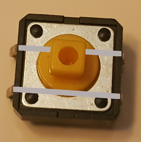
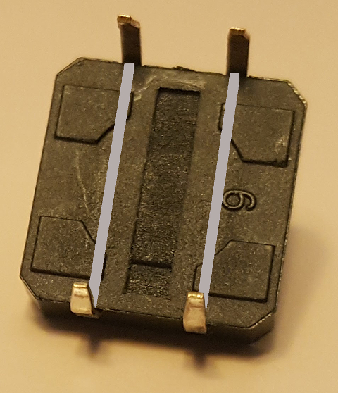
When the button is pressed, the two parallel wires are connected together - so all four pins are electrically connected when the button is pressed. When we press the button we are not connecting the pin on the opposite side - we are connecting the pin on the adjacent side.
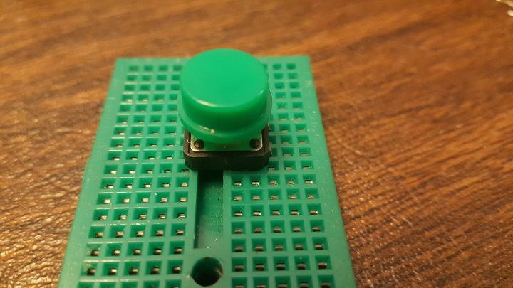
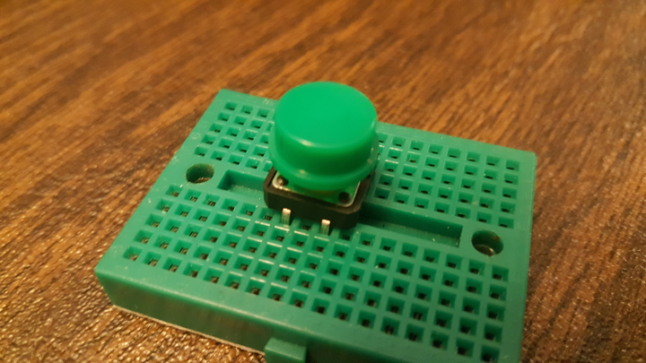
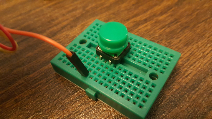
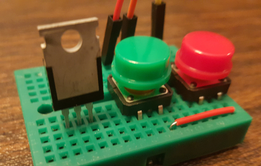
To begin wiring up our button, let's push our button onto the mini breadboard. This button should act as a bridge over the middle, empty space within our breadboard. One half of this breadboard is not electrically connected to the other half... unless we use a button or a wire as a bridge. When the button is pressed into the breadboard, all the pins on one side should be on one half of the breadboard:
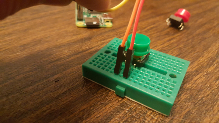
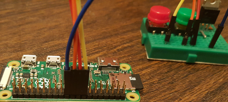
Next, let's connect the one pin on the button to a ground pin on the Raspberry Pi. Using a jumper wire, connect a pin on the button to a the Ground pin on the Raspberry Pi that is just above the pin for GPIO #23 (it's pin #14 on gadgetoid's interactive pinout diagram). Let's pick the closest ground pin to the GPIO pin we just used:
Finally, to complete this button's circuit we need to connect GPIO pin #23 on the Raspberry Pi to the other side of our button. Connect your jumper wire to pin #16 on the row of GPIO pins:
Let's add a second button as well. Note that we can have all of our buttons and switches share the same ground pin, which cuts down on the number of wires going back and forth. We will wire the new button to GPIO pin #24 (pin #18)...
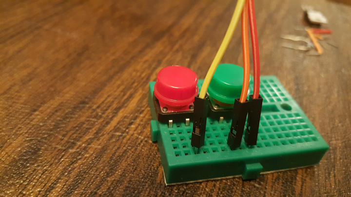
...and then will add some short wire to our mini breadboard to connect our new button to ground:
Output (Switches)
Now that we've wired up a few buttons, let's connect a switch that we can turn on or off.
For my low-voltage applications, I usually use an N-type MOSFET instead of a mechanical relay. You could even use an NPN transistor for some applications. Of course, a mechanical relay is fine as well. I would recommend learning more about the benefits of each; if you are looking to pick up some research material, I'd recommend Make's Electronics 2nd Edition, which may well be in your local neighborhood library (remember those?) or available from your local artesinal bookstore.
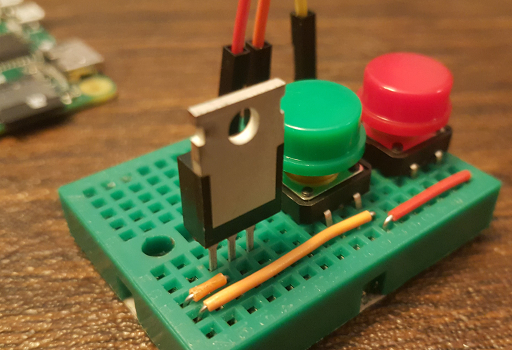
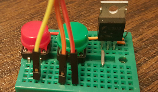
The following guide will use a MOSFET for low-impact usages (like flipping on a few LEDs), and starts with inserting its three pins into the breadboard:
A MOSFET has three pins: the gate, the drain and the source. The big metal fin on the back is sometimes used as the drain as well. When you energize the gate, you allow the source to be connected to the drain. It's like folding a kink in a garden hose - you stop things from draining into the yard by folding the hose, then you open it up to allow the source water fountain to finally drain to the ground.
We are going to connect our gate to GPIO #25 on our Raspberry Pi:
Then we let the drain connect to our shared Ground pin:
We also need to use a 4.7k resistor from the gate down to ground:
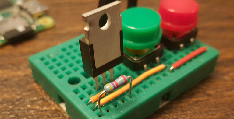
Next we will create a bridge from the source pin of the MOSFET, across one half of the breadboard, to the other side. We don't have anything to switch on yet - but now we have a nice & tidy way to connect something like an LED to ground!
Nicely done! Now if you load up the Adding Buttons to Push lesson, you can press the buttons to zero out your display!
Next up - wire up your amplifier & speakers!