Wiring Up the Audio Amplifier & Speakers
An alarm clock isn't much of an alarm clock if it doesn't have a shrill little scream to wake you up. On this step we will wire up a digital audio decoder, amplifier and a 2-channel mono speaker.
You will notice on Model A's and Model B's of the Raspberry Pi there is a headphone jack that you could possibly amplify and drive a speaker with. The first version of the Hack Clock did wire a TTRS jack to a small amplifier, and then drove a small mono speaker. However, the headphone jacks were cumbersome, required some careful soldering skills, and the sound interface wasn't that reliable. Some times the audio alarm just wouldn't power up!
With this edition of the Hack Clock we are using digital audio output from the Raspberry Pi, following the Inter-IC Sound Bus (I2S) standard. Adafruit sells a very efficient I2S decoder and amplifier in one tiny package based on the MAX98357A chip. This actually reduces the part count, is cheaper and so far is more reliable!
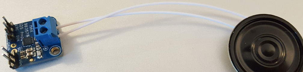
Let's connect the speaker first. I use small speakers (either 4Ω or 8Ω) like you would find in a toy or a greeting card. Those tiny speakers can't drive too much sound before they clip out & issue nothing but static, so it helps to have a speaker housing for them.
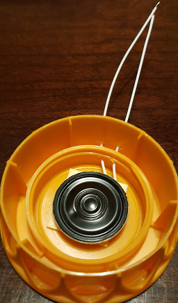
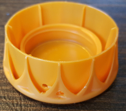
My favorite cheap speaker housing is a plastic cap from a milk or orange juice bottle. After drilling a couple of small holes in the side and using some double-sided tape, I inserted the speaker into the cap and thread the wires through the holes. Now we can get louder!
Next, we can screw the speaker wires into the screw-in terminals on the Adafruit breakout board. The order of the wires doesn't really matter since we are using a single speaker.
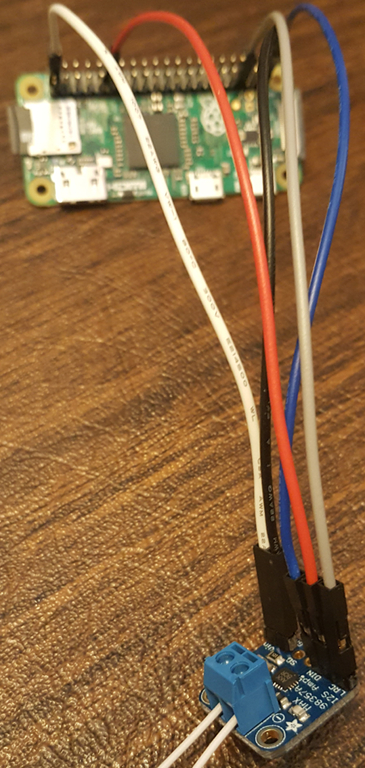
After this we need to provide power and data to our MAX98357A breakout board. Unfortunately the wiring from the board to the Raspberry Pi pins isn't nice and organized - it spreads across the board.
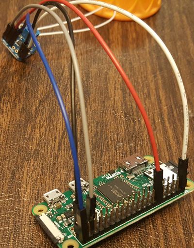
Let's connect with:
- Connect the Vin pin on the amp to the +5V pin (pin #2) on the Raspberry Pi
- Connect the GND pin on the amp to the Ground pin (pin #39) on the Pi
- Connect the DIN pin on the amp to GPIO 21 (SCLK) (pin #40) on the Pi
- Connect the BCLK pin on the amp to the GPIO 18 (PWM0) (pin #12) on the Pi
- Connect the LRCLK pin on the amp to the GPIO 19 (MISO) (pin #35) on the Pi
Phew. Done! If we load up Lesson 4: Play Music, or if we SSH into the Raspberry Pi and execute:
speaker-test -c 2
we should be able to hear some sound! The Hack Clock ships with a test audio track so you can try things out.
Finally, the best part - building your enclosure!