Connecting the 7-Segment LED Display
The LED display and the "backpack" logic board ships in two separate pieces from Adafruit - follow the instructions at https://learn.adafruit.com/adafruit-led-backpack/1-2-inch-7-segment-backpack to solder the pieces together. Don't worry about the "Seven-Segment Backpack Firmware" section - at this point we just need to solder the pins correctly and connect the wires to our Raspberry Pi.
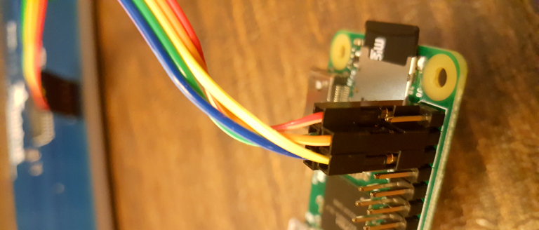
To wire up the LED display to the Raspberry Pi you need to grab a five jumper wires of varying colors. The actual color doesn't matter at all... however sometimes it is helpful to stick with a color scheme. By using the same colors each time, you can more easily determine what each wire is supposed to do.
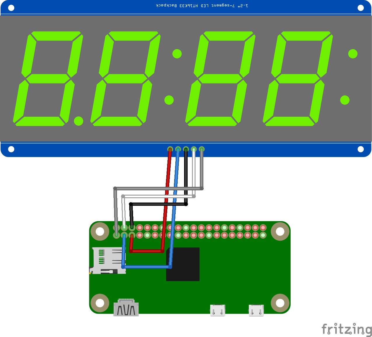
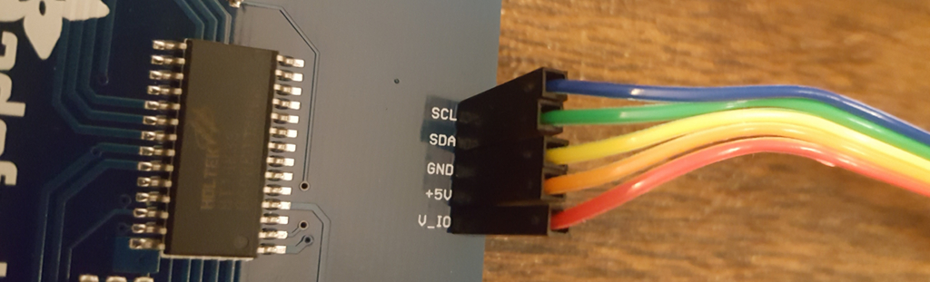
To wire up the Adafruit 7-Segment LED backpack to a Raspberry Pi:
- Wire the VIO (I/O power) pin on the display to Pin #1 (3.3V power) on the Raspberry Pi using a red jumper cable
- Connect the +5V (LED power) pin on the display to Pin #4 (5V power) on the Raspberry Pi with an orange jumper cable
- Wire the GND (Ground) pin on the display to Pin #6 (Ground) on the Raspberry Pi using a yellow jumper cable
- Connect the SDA (I2C Data) pin on the display to Pin #3 (SDA) on the Raspberry Pi using a red cable
- Connect the SCL (I2C Clock) pin on the display to Pin #5 (SCL) on the Raspberry Pi with a blue cable
Once the display is wired up, double-check your connections and power on your Raspberry Pi. If you have loaded Lesson One of the Hack Clock on the Pi, you should see a lit-up display with three 0's!
Next up - create some buttons and switches for your display!